Installation
Three short stories from a real PhloMetric deployment: how a Node gets its power without a new outlet, how the enclosure mounts on the property, and the off-the-shelf box it all lives in. None of this requires an electrician, a service truck, or downtime on the irrigation controller.
Before you start · Confirm your meter has a readable endpoint
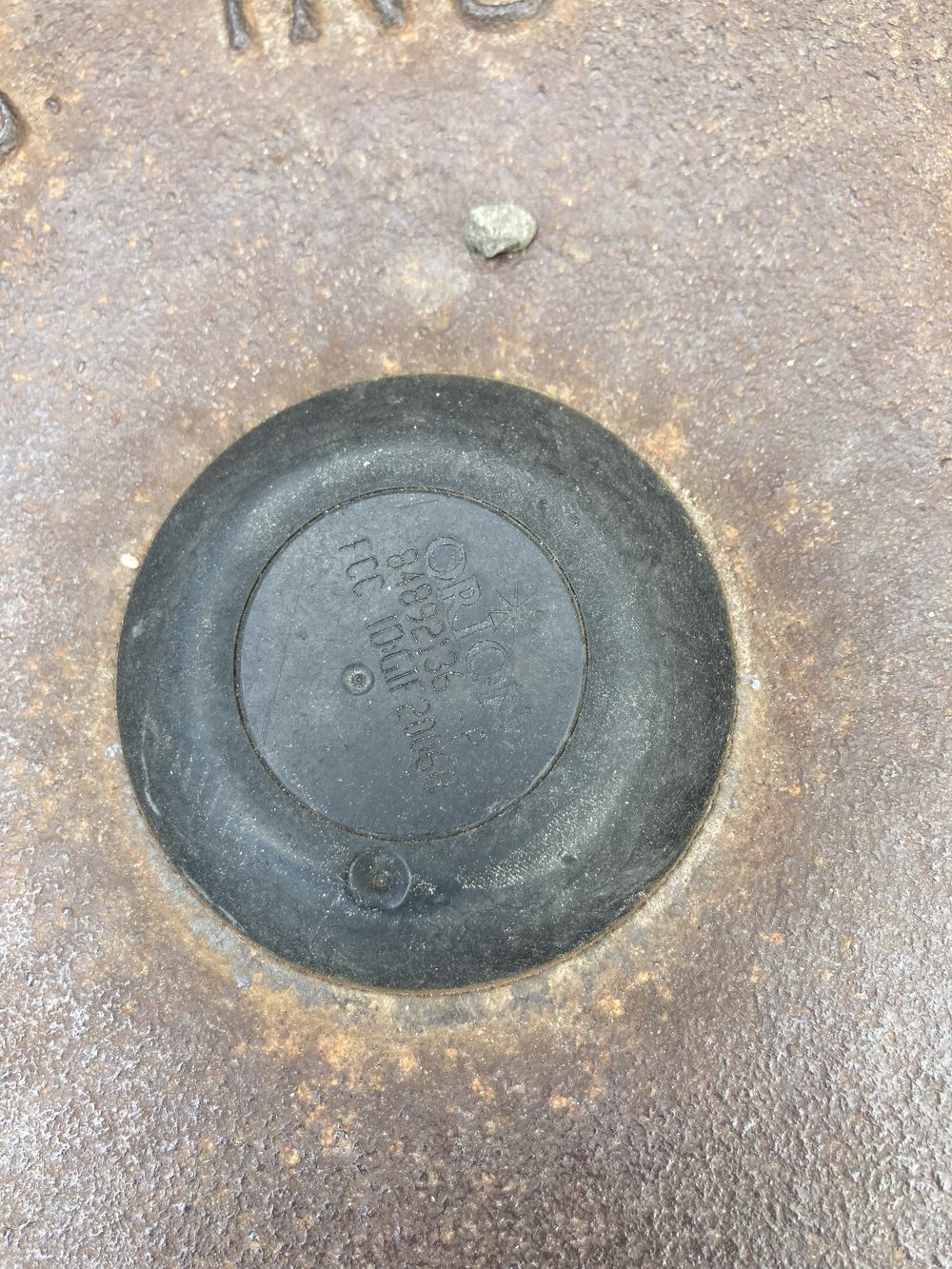
The Node reads a radio endpoint that the utility has fitted to the meter. Before ordering hardware or planning a deployment, check that the meter you want to read actually has one. Lift the meter well cover (the cast-iron or composite lid set into the ground at the property line) and look at its center: a compatible installation has a round plastic disk seated in the middle of the lid, like the one below. That disk is the ORION radio endpoint; it is what the Node hears over 900 MHz. No disk, no signal to read.
The disk is usually black, a couple of inches across, and molded with an ORION logo plus an FCC ID. If your lid is solid cast iron with nothing in the center, the meter is a non-transmitting (touch-read or fully manual) type, and this system cannot read it as-is. If you find the disk, note the meter's serial number; you will select it as your default meter during setup.
If the plastic endpoint mount in the lid is worn, obscured, or unmarked, you can still identify the meter two ways, by lifting the endpoint out of the well. The endpoint type is printed on the endpoint body itself: read its FCC label to learn which ORION model, and therefore which protocol, you are dealing with. And as long as the endpoint has not been pulled from its data wire, the meter ID is on a small barcode label clipped to that wire; that serial number is the one you select as your default meter during setup.
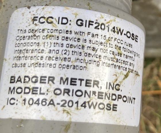
FCC ID: GIF2014W-OSE, a Badger ORION endpoint; other units read GIF2006B or GIF2020OCECNA. That GIF model is the reliable way to identify the meter type when the lid disk is unreadable, and it is the type you select on the Node's setup page.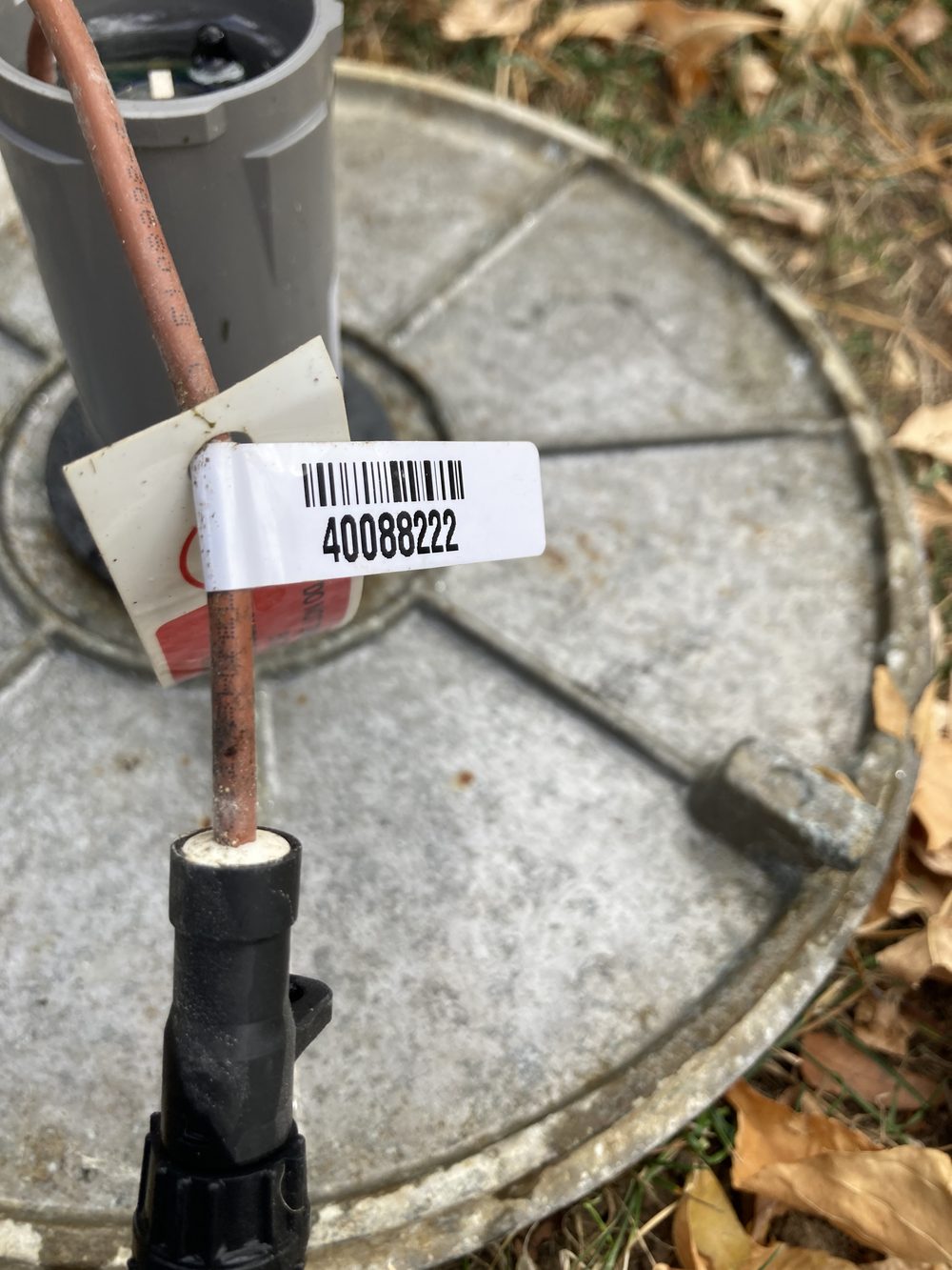
40088222). That is the ID you pick as your default meter on the Node's setup page, so the Node locks onto your meter and ignores the neighbors'.1 · Tapping 5VDC from the irrigation controller's 24VAC
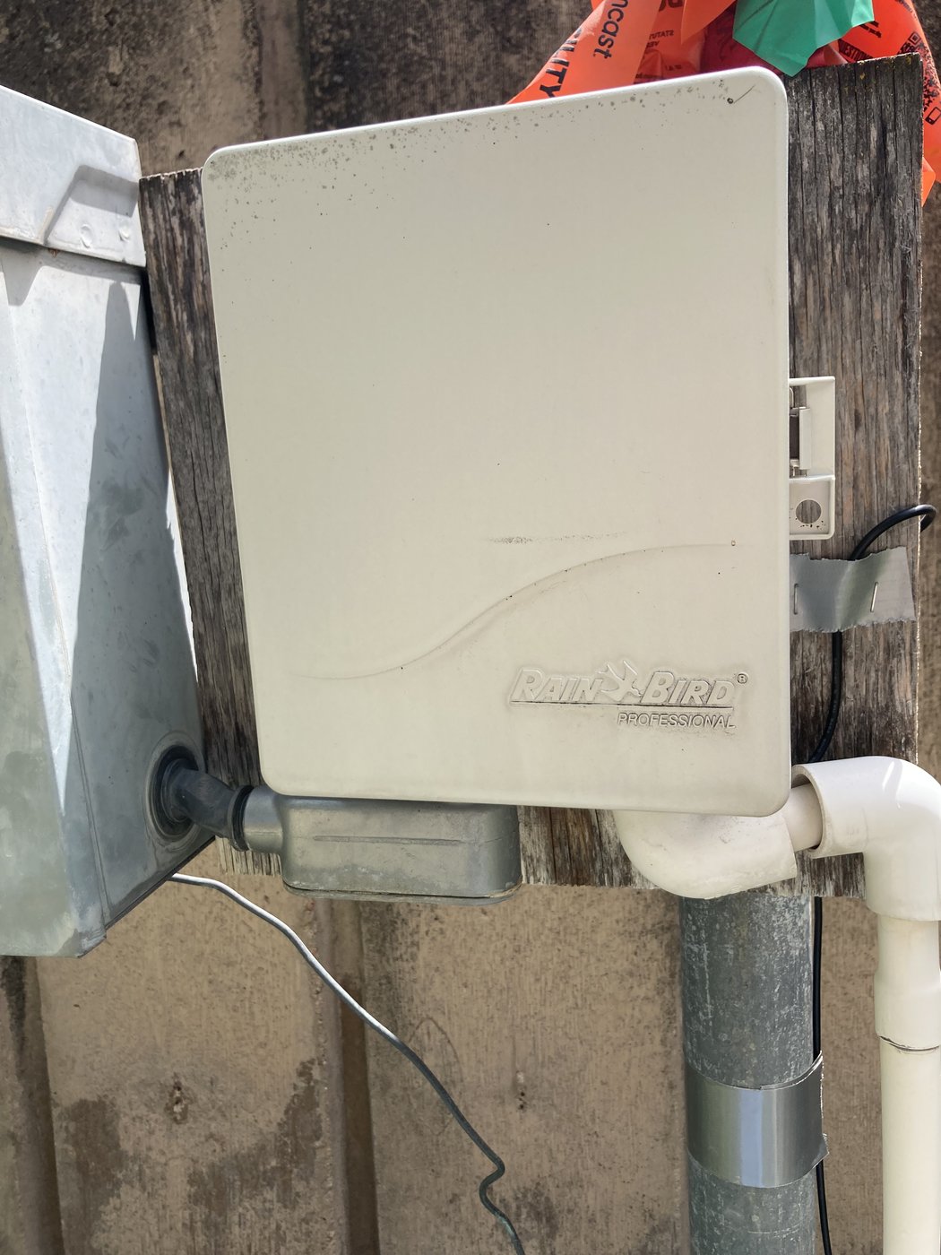
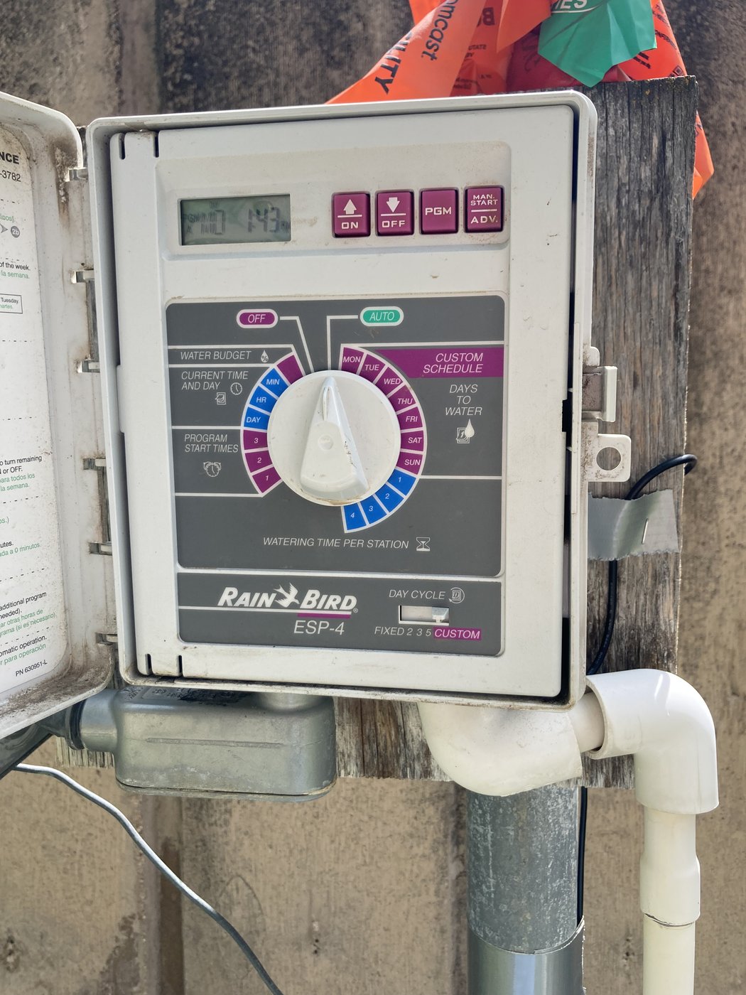
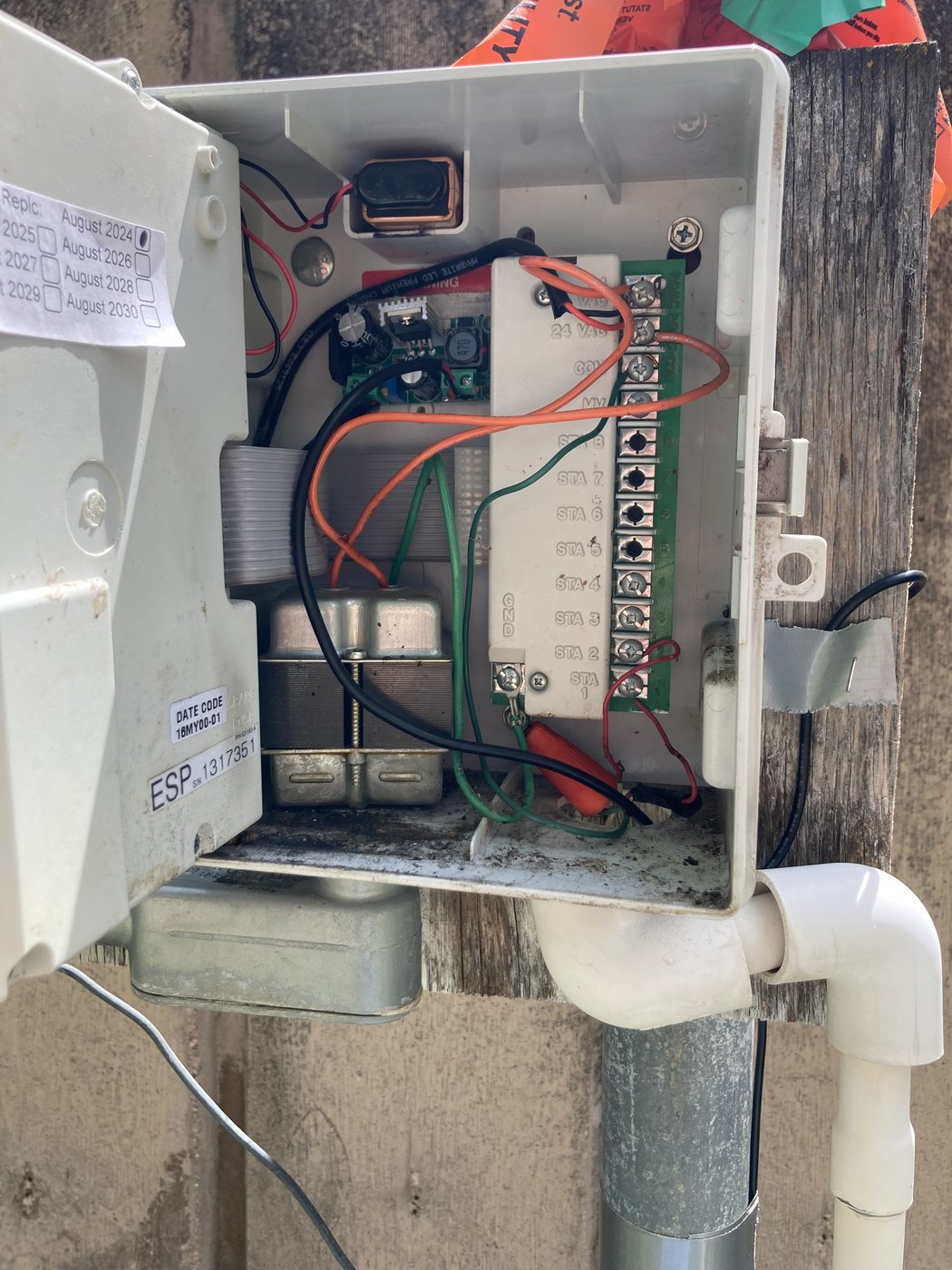
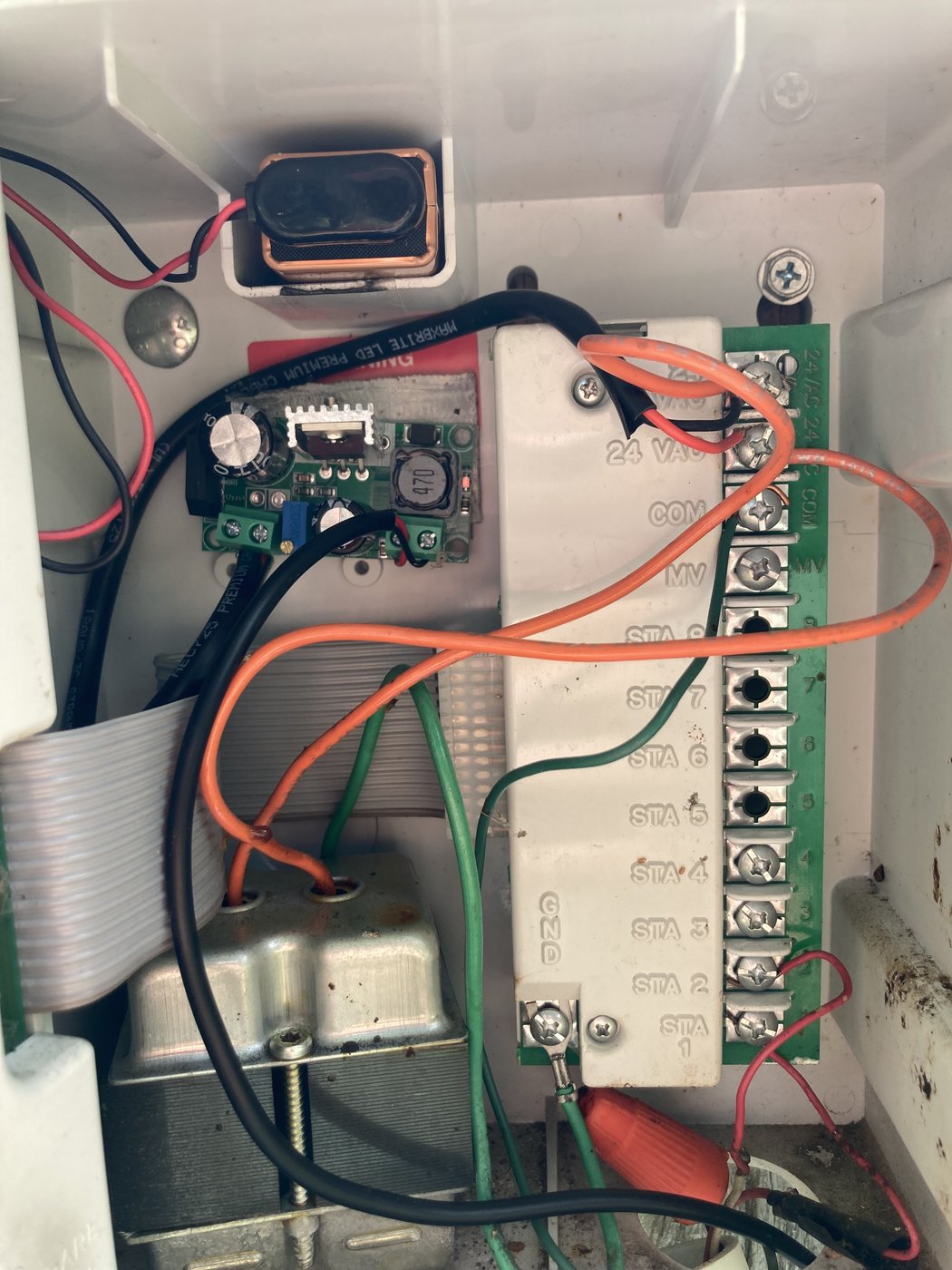
A residential irrigation controller already has the two things a Node needs: weatherproof housing on an outside wall, and a permanent 24 VAC supply for its solenoid valves. We piggyback on both. A small AC→DC buck module rectifies a tap off the 24 VAC bus to a clean 5 V, which feeds the Node sitting a few feet away. No new conduit, no new outlet, and the irrigation controller keeps working untouched.
Total parts added inside the controller: one buck module and four short wires. Five-minute job.
2 · Mounting the Node on the property
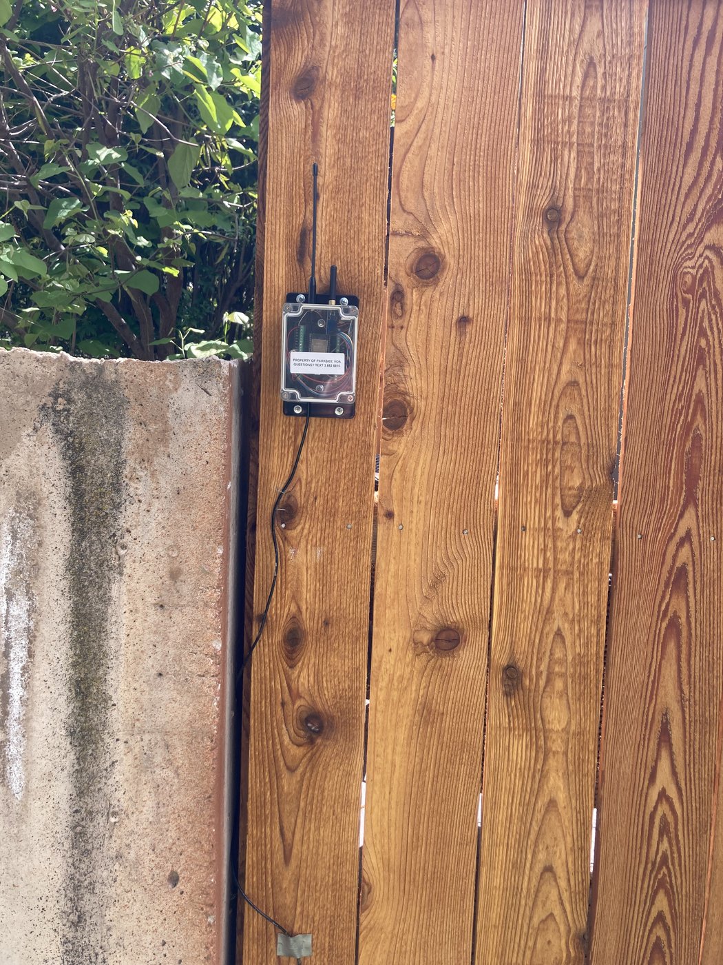
The Node enclosure is small enough to disappear under a deck, on a fence post, or on the back of a garage, anywhere it has line-of-sight to the water meters and a power feed from the controller a few feet away. The photos below show one real install, going from wide property context down to the box itself.

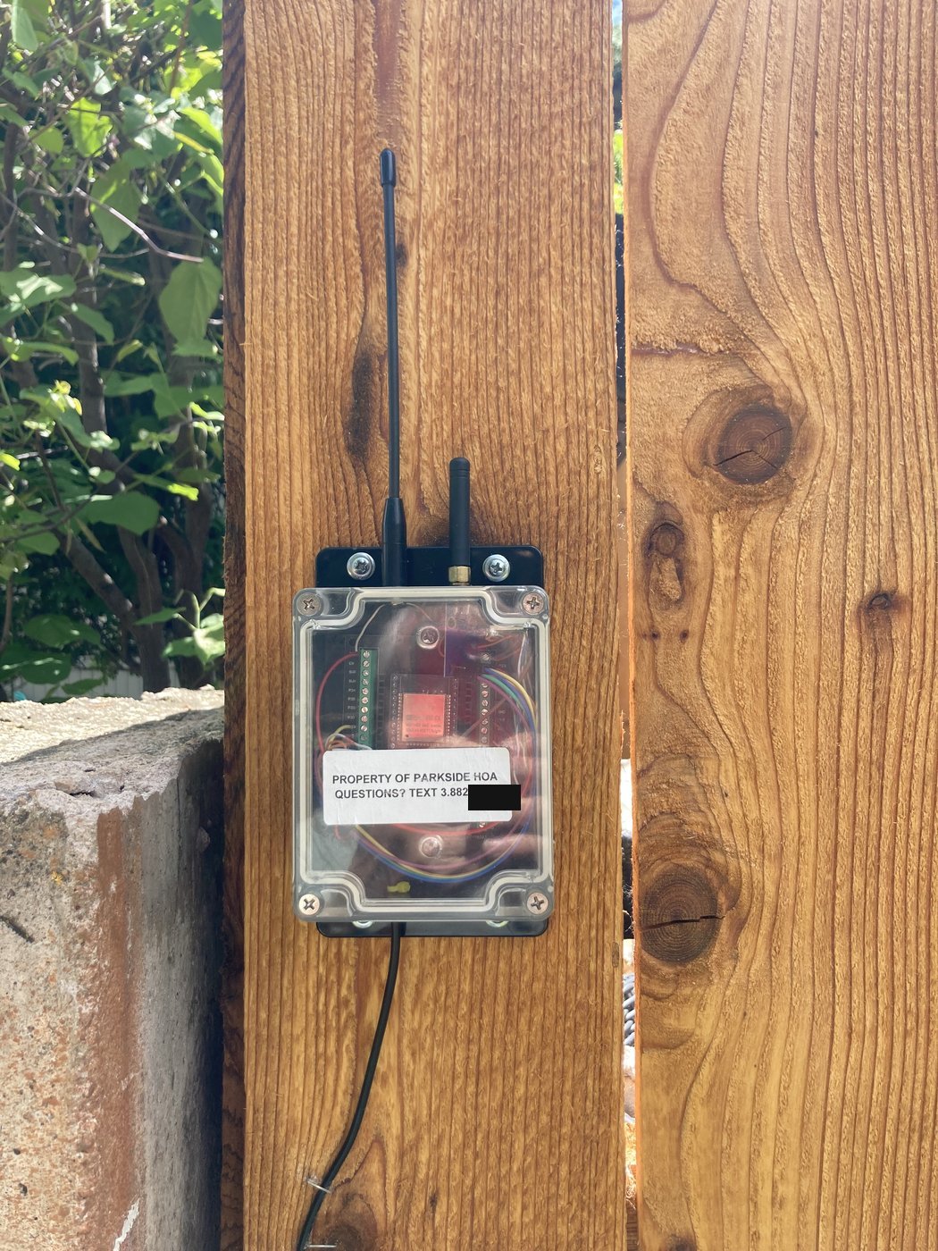
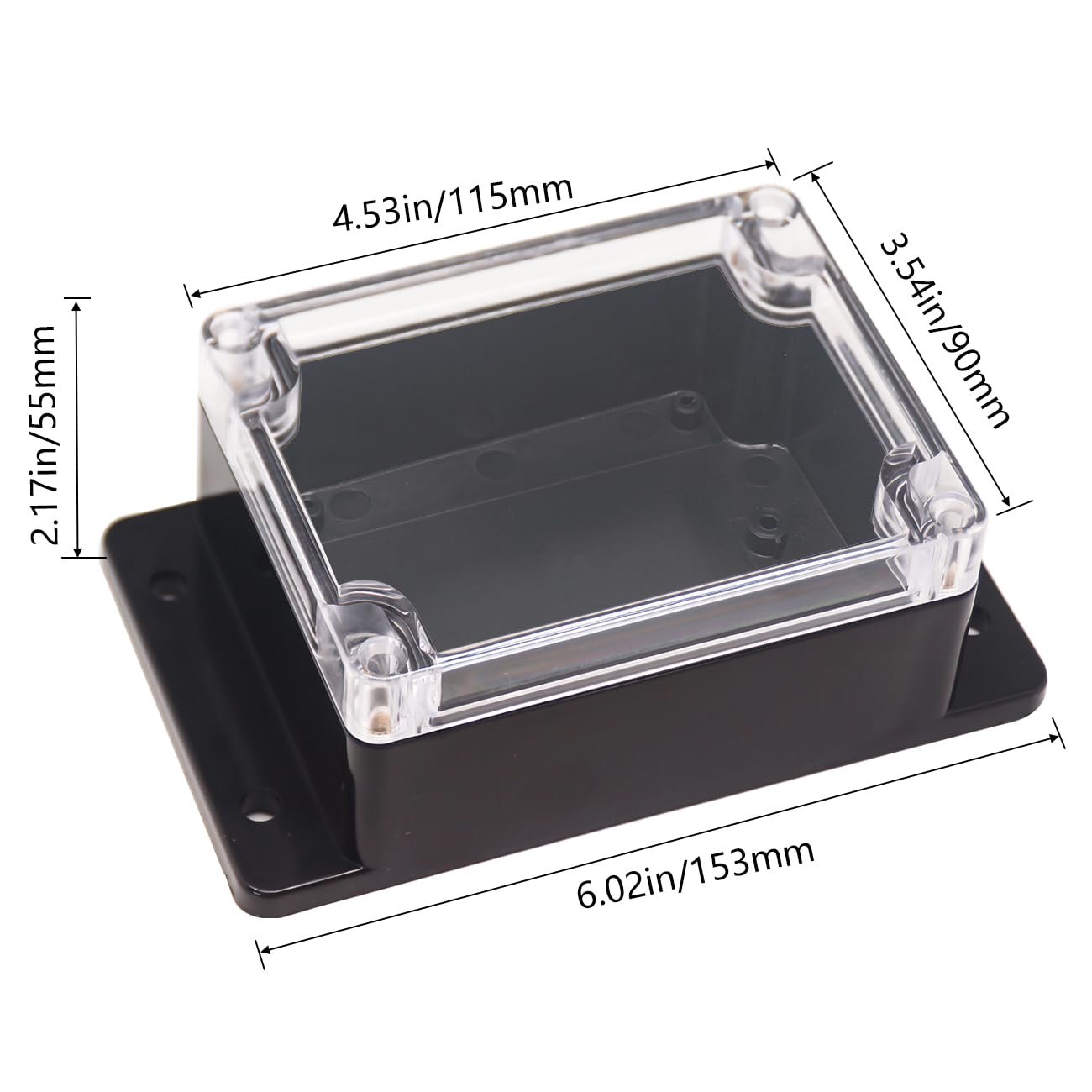
3 · The enclosure
Nothing custom: an off-the-shelf clear-lidded ABS project box. Flanged mounting tabs make it screw-mountable straight to any flat surface; the clear lid means the antenna pattern isn't blocked by metal and you can see the status LEDs without opening it up.
What about the rest?
The radio and software side of this Node (protocol decoding, dashboard, emails) is covered on the Node page. If the Node is one of many feeding a central database, the upstream side is the Gateway. For an example of what an installed Node mails out every morning, see the Email sample.